This page shows some recent results from our project to build a 3D fax machine. To look at results from our other projects, browse through our list of current research projects. Or you can return to our home page.
There is a growing interest in the graphics, machine vision, and manufacturing communities in building a 3D fax machine, an inexpensive device capable of digitizing the shape and external appearance of an object. Applications for such a device include product design, fast prototyping, reverse engineering, medical scanning, and digitizing of shapes for the visual simulation, animation, and entertainment industries.
Acquiring shape and appearance requires solving an inverse rendering problem: given a set of images, solve for scene illumination, sensor geometry, object geometry, and object reflectance. If the images are acquired using passive sensing (such as a video camera), this is a hard problem. The difficulty arises in large part from the necessity of finding corresponding features in multiple images.
On the other hand, if the images are acquired using active sensing (such as a light stripe scanner), the problem is greatly simplified. In particular, by limiting the problem domain to a stationary scanner for small objects, we can control sensor geometry and scene illumination, thereby eliminating several variables from the problem. By employing active sensing using structured light, we can independently measure geometry and reflectance, thereby eliminating even more variables. Finally, by providing computer control over the operation of the scanner, we can acquire redundant data, improving the robustness (i.e. error tolerance) of the system.
In the demo images and movies above, we used a modified triangulating laser stripe range scanner (built by Cyberware Inc. of Monterey, California) and a precision motion platform.
The goal of optically-sensed 3D shape digitization is to produce a seamless, occlusion-free, geometric representation of the externally visible surfaces of an object. There are many active optical sensing devices on the market that can digitize the shape of one side of an object. These devices are generically called range finders. Their output is called a range image - a rectangular lattice of pixels each of which contains a distance Z from the sensor to the object at that X,Y location.
A harder problem is to digitize objects having multiple sides and self-occlusions (i.e. parts that obscure other parts). Several methods have been proposed that solve this problem by scanning the object from several directions and combining data from the individual scans. In our laboratory, we have investigated methods based on fine-grain polygon meshes and 3D voxel arrays with an occupancy probability at each voxel. For this demo, we used polygon meshes.
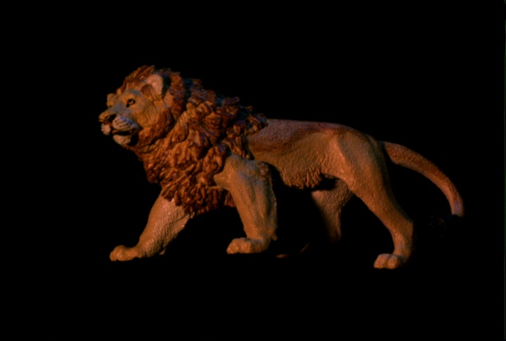
Our test object was a plastic toy lion 25cm long. By placing the toy lion in various orientations (including lying on its side) on our motion platform, we obtained 14 high-resolution range images (512 x 512 depth samples) aligned with submillimeter precision that covered (with much redundancy) the entire surface of the toy.
To combine the information from these aligned range images, each range image was converted to a polygon mesh having as many polygons as the range image had depth samples. Neighboring meshes were aligned using the known motion platform location and an automatic shape matching algorithm, then zippered together. The entire method is described in Greg Turk and Marc Levoy, Zippered Polygon Meshes from Range Images, Proc. SIGGRAPH '94 (Orlando, Florida, July 24-29, 1994). In Computer Graphics Proceedings, Annual Conference Series, 1994, ACM SIGGRAPH, pp. 311-318.
The result of this zippering process is a single mesh that completely describes the object. A few small holes resulting from unreached portions of the surface were filled by hand. The final mesh contained 270,000 triangles. Assembling it took about an hour of scanning, a few minutes of user time to roughly align the scans, and several hours of hands-off processing time (on a MIPS R4000).
The amount of light reflected from a surface depends on the direction of illumination and the direction of reflection. Each of these two directions consists of two angles. The resulting four-dimensional function is called the bidirectional reflection distribution function (BRDF). It typically varies with the wavelength of the illumination. For textured objects, it also varies from point to point on the object's surface.
Like shape, the BRDF of an object can be acquired from multiple images and pieced together. For each surface radiance measurement (corresponding to a pixel on an image), the first step is to calculate the irradiance falling on that portion of the surface. Irradiance depends on the location and orientation of the surface and the location and shape of all light sources. In our system, these geometrical quantities are known, so this calculation is straightforward. Note that irradiance must be corrected for any shadows cast on the surface by other parts of the object. Here again, knowing the geometry of the object and the light sources makes the task straightforward. The second step is to calculate surface reflectance from the known irradiance, the measured radiance, and the geometry of the scene. Each such measurement provides one data point in the object's spatially-varying BRDF.
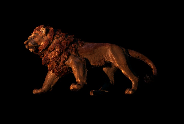
The toy lion used in this demo was hand-painted and exhibited a uniform satin finish. A painted surface like this consists of dye particles suspended in a homogeneous transparent medium. The BRDF of such a surface has a simple form consisting of two components: a mirror-like but colorless reflection from the smooth surface of the paint and a diffuse but colored scattering of light from the suspended dye particles.
We measured surface radiance using a color CCD camera built into our Cyberware scanner. For each range image acquired by the scanner, a color image of comparable resolution was also acquired. We then computed irradiance and reflectance as described above. The latter was separated empirically into two components in keeping with our assumed model of the surface material. The algorithms used for this computation are still under development and are not described in the paper by Turk and Levoy. The output of this step was an RGB color for each of the 147,000 vertices of the zippered mesh. The time required to scan the color information is folded into the scanning time listed above. Color correction required several hours of processing time on a MIPS R3000-based SGI VGX workstation. The graphics hardware of the VGX was used to accelerate shadow calculations.
To generate images of the digitized lion, we rendered our zippered polygon mesh using Pixar's RenderMan software. Lights and the camera were placed according to measurements made from the real scene. Illuminant intensities and colors were selected by eye to match the real scene. We recreated the colorless reflectance of the plastic surface using RenderMan's standard plastic surface shader, with reflectance parameters selected by eye to match the real lion. These parameters were modulated on a per-vertex basis according to the scattered color computed for each vertex as described above. The scene was rendered with shadows and stochastic spatial supersampling, but without motion blur. The motion in the movie sequence was matched to that of the motion platform used in the real scene. Each frame of the movie took 25 minutes to render on a MIPS R4000 and required 128 MB of memory.
The meshing software was written by Greg Turk. The color acquisition software was written by Hua Ge. The renderings were done by Marc Levoy, who also wrote this web page. We acknowledge the advice and help of the staff of the 3D fax project, David Addleman and George Dabrowski of Cyberware, and Andy Hung and Sarah Beizer of the Computer Systems Laboratory. We also acknowledge the financial support of the National Science Foundation, the Powell Foundation, IBM, SoftImage, and Interval Research.