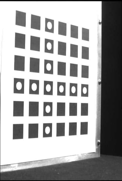
Input image
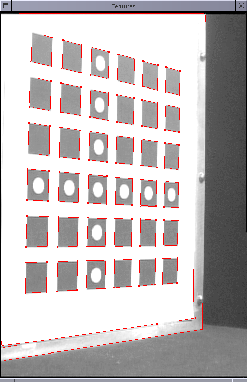
Detected features
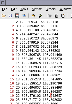
Output file of corner coordinates
Input image |
Detected features |
Output file of corner coordinates |
Detecting the sub-pixel coordinates of image features, such as the corners of a calibration grid, is the first stage any camera calibration algorithm. This grid detector was built as part of the metric calibration pipeline of the Stanford Multi-camera array which consists of 100 cameras. However, this has been used in several other projects in our lab and by some of our colleagues elsewhere, such as:
The key strengths of our grid detector are:
We have successfully used the grid detector on images from different kinds of cameras (including those from our array, a Canon EOS D10, an Olympus 3000Z, Sony DKC-ST5, consumer webcams) on over 10,000 images.
usage: findgrid <image file> <grid file> <-f config file> [-e|c] [-p side space rows cols] [-t threshold]
findgrid:
Linux binary executable, download here.
image file:
File containing image you want to run the grid detector on. PPM, PGM, PNG, JPG formats are supported.
grid file:
File name in which the output of the grid detector is written. The output grid file contains
the (x,y) coordinates of the corners of grid squares detected, one corner per line. The line format is:
corner-number x-pixel coordinate y-pixel coordinate
Here is an example of a grid file. The corner numbers start at 0, and increase in row-major order. For the 6x6 grid in the example above, there are 6 x 6 = 36 squares and hence 36 x 4 = 144 corners. The top left corner is numbered 0 and the bottom right is 143.
config file:
File containing configuration parameters for the grid detector, download here. To be edited
only by developers.
-e|c (optional):
This flag controls the edge detector used. -e results in the use of the Palmer edge detector, which is
the default. -c results in use of the Canny edge detector. This is recommended only if the grid squares
are large (more than 100 pixels x 100 pixels) in the image or axis aligned. I suggest you try both and go with whichever
works better for your images.
-p side space rows cols (optional):
Specifying the geometry of the calibration grid used for verification. side refers to the length of the side
of each of the grid squares, space is the distance between two adjacent squares in the same row or column. It
is necessary to use the same unit of length for both.
rows and cols are the number of rows and columns in the grid.
threshold: (optional)
When the calibration grid geometry is specified with -p, a 2D projective mapping (also called a homography
or collineation) is computed between the detected grid squares and the specified calibration grid geometry and the RMS
error (in pixels) of the mapping is computed. The user supplied threshold is used to verify the correctness
of the grid detection. If the grid has been correctly detected, the RMS error should be small and below the threshold.
In rare cases, the grid detector can miss an entire row or column of squares. This is where the geometry verification is
useful: the RMS error is high, and should exceed the threshold, in which case the program will print an error
message and no grid file will be written. The default threshold is 1.0 pixel, for correctly detected grids the RMS error
averages around 0.35 pixels.
-p unless there is a good reason not
to, such as severe radial distortion.There are two files you need to download:
findgrid
| File Name | Square Side (mm) | Square Spacing (mm) | Total Area (mm2) |
| biggie.pdf | 100 | 50 | 850 x 850 |
| regular.pdf | 50 | 30 | 450 x 450 |
| small.pdf | 20 | 10 | 170 x 170 |
| tiny.pdf | 9 | 6 | 84 x 84 |
Grids of any sizes may be used provided they meet the following criteria:
[2] Phil McLauchlan. Horatio: a computer vision and image processing library.
[3] Phil McLauchlan. Gandalf: a computer vision and numerical algorithm library.
[4] OpenCV computer vision library.
© Vaibhav Vaish
Last update:
January 5, 2006 11:38:23 PM