CS348B Final Project
Matthew Wang
Part I - Project Proposal:
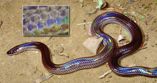
As its name suggests, the sunbeam snake (Xenopeltis unicolor) produces a brilliant iridescent sheen when exposed to bright sunlight. Intrigued by this unusual display, I thought it would make an excellent final project for CS348B. The purpose of my project was to simulate the appearance of the sunbeam snake, through modeling the thin-film interference behaviour of light and procedurally generating scales to cover the body.
 Part II - Iridescence:
The major rendering component of the projet was creating a BRDF within PBRT that would simulate iridescence. This first required understanding the phenomenon. The diagram below illustrates the path a ray takes when encountering a thin film. Here the ray enters from the left and exits on the right. While some of the light is reflected from the top of the surface, the rest is transmitted through the film and reflects off the bottom of the surface. Note the application of Snell's law [n1sin(theta1) = n2sin(theta2)] to acquire the new direction of the transmitted ray.
As a result of the film, the separated rays take two different paths before leaving to the right. The difference in length of these two paths offsets the wavelength of the rays, resulting in interference. Furthermore, the difference in index of refraction between the material that a ray is traveling in and the material it strikes can result in a half-cycle phase shift.
Part II - Iridescence:
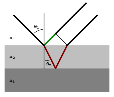
The major rendering component of the projet was creating a BRDF within PBRT that would simulate iridescence. This first required understanding the phenomenon. The diagram below illustrates the path a ray takes when encountering a thin film. Here the ray enters from the left and exits on the right. While some of the light is reflected from the top of the surface, the rest is transmitted through the film and reflects off the bottom of the surface. Note the application of Snell's law [n1sin(theta1) = n2sin(theta2)] to acquire the new direction of the transmitted ray.
As a result of the film, the separated rays take two different paths before leaving to the right. The difference in length of these two paths offsets the wavelength of the rays, resulting in interference. Furthermore, the difference in index of refraction between the material that a ray is traveling in and the material it strikes can result in a half-cycle phase shift.
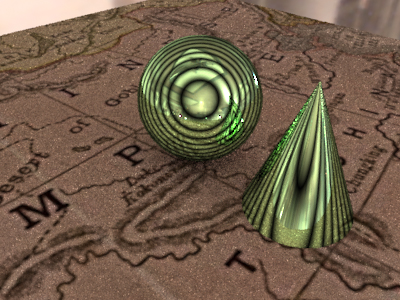
 If the difference in wavelength is an integer multiple of half a period, we get destructive interference, where the amplitudes of the waves cancel each other out. On the other hand, if the difference in wavelength is an integer multiple of a full period, we get constructive interference, where the resulting amplitude is the sum of the two amplitudes. The image below shows the results of this interference, under the assumption of monochromatic light. The green coloration is due to the underlying color of the material.
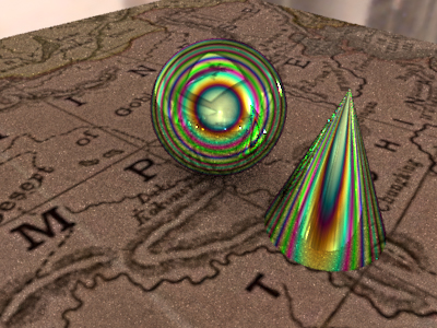
 To achieve the beautiful coloration characteristic of thin films, we must take into account the effects of different wavelengths. Due to the fact that the index of refraction of a material is a function of wavelength, along with the fact that the wavelength compression changes the cycle offset, each wavelength exhibits different interference patterns, which overlap to create a wide display of different colors. My model makes the assumption that we are always using white light, thus presenting us with the full color spectrum.
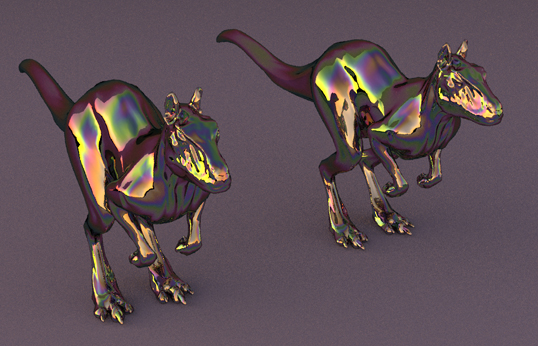
 After tweaking the various parameters (e.g. film thickness, indices of refraction, etc.) I was able to obtain a decent effect, which I tested out on the provided "killeroo" model.
 Part III - Making Scales:
I wanted to provide the artist with fine control over the appearance of the scales. For this reason, I decided to allow the artist to create a single scale model and import this as a .obj file. Isolating the scale geometry in this way would allow for easy tweaking at any time. To implement this capability, I created a new Shape subclass in PBRT that could read in a simple .obj file and create a TriangleMesh shape from the geometry.
Part III - Making Scales:
I wanted to provide the artist with fine control over the appearance of the scales. For this reason, I decided to allow the artist to create a single scale model and import this as a .obj file. Isolating the scale geometry in this way would allow for easy tweaking at any time. To implement this capability, I created a new Shape subclass in PBRT that could read in a simple .obj file and create a TriangleMesh shape from the geometry.
 Of course, loading thousands of scales into the system would require a lot of memory if redundant information were not eliminated. Preliminary tests without fixing this problem were slow and could only render several hundred scales before running out of memory. To solve this problem, I took advantage of the Object Instancing capabilities provided by the PBRT scene file specification. This required writing a separate C++ program to generate the scene file. Early testing showed that this was far faster and was able to support thousands of scales.
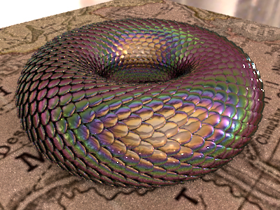
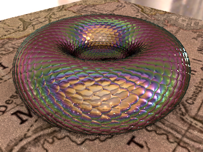 The program I wrote provided easy control over properties of the scales such as vertical and horizontal density, as well as protrusion angle, as demonstrated below.
 Part IV - Making The Snake:
The final step was to define the actual shape of the snake. Again, I wanted to provide the artist with a high level of control in this regard. Furthermore, I wanted to develop a system that would easily support animation. To accomplish this task I chose to use Bezier curves. Rather than reinvent the wheel, I used existing code to define the curve based on a set of control points. I then created a Bezier class and incorporated this into an interactive 2D OpenGL program that allows the user to add, remove, and place control points in the scene.
Part IV - Making The Snake:
The final step was to define the actual shape of the snake. Again, I wanted to provide the artist with a high level of control in this regard. Furthermore, I wanted to develop a system that would easily support animation. To accomplish this task I chose to use Bezier curves. Rather than reinvent the wheel, I used existing code to define the curve based on a set of control points. I then created a Bezier class and incorporated this into an interactive 2D OpenGL program that allows the user to add, remove, and place control points in the scene.
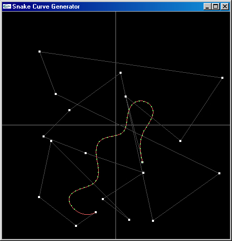 The red line shows the entire path defined by the control points, while the green dots represent the actual length of the snake. The reason for this representation is so that an animation path can be specified (the red line), while providing the user with a quick visual reference of the snake's length.
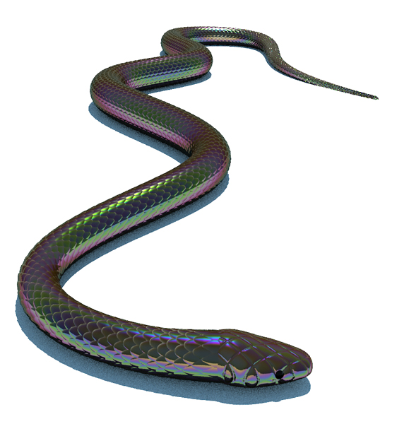
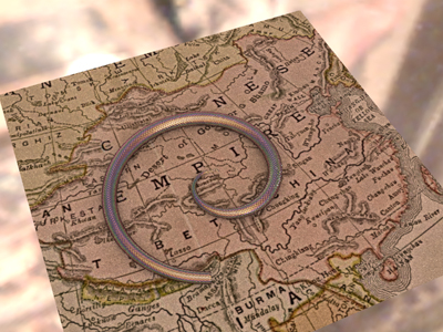
Once the user is satisfied with the curve, the program outputs a scene file with the appropriately transformed instances of each scale to model the shape of the snake. The tapering of the snake's girth to create the tail and neck was accomplished through the use of specially designed mathematical functions. I chose functions such that the derivatives were continuous at each joint (e.g. between neck and body, body and tail).
The red line shows the entire path defined by the control points, while the green dots represent the actual length of the snake. The reason for this representation is so that an animation path can be specified (the red line), while providing the user with a quick visual reference of the snake's length.
Once the user is satisfied with the curve, the program outputs a scene file with the appropriately transformed instances of each scale to model the shape of the snake. The tapering of the snake's girth to create the tail and neck was accomplished through the use of specially designed mathematical functions. I chose functions such that the derivatives were continuous at each joint (e.g. between neck and body, body and tail).
 Part V - Finishing Touches:
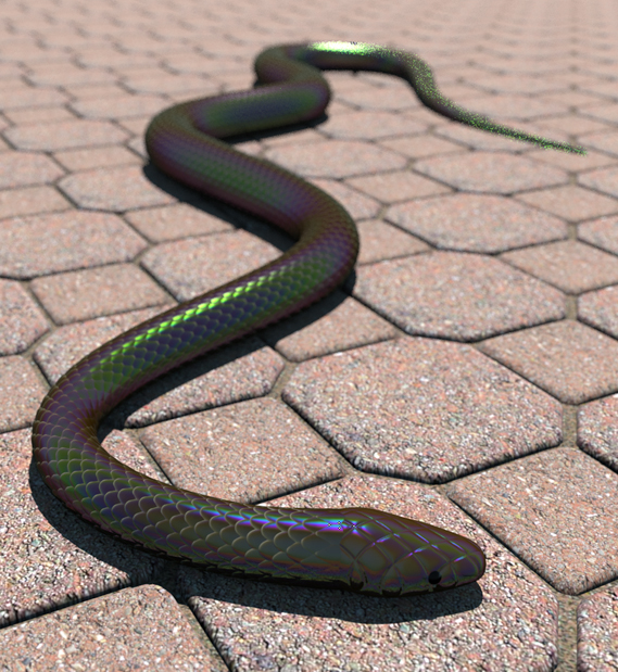
Once I had finished creating all the necessary elements of the snake, I had to tweak all the parameters, design a more appropriate scale model, shape a realistic curve, add a head, and texture the model. I also played around with the lighting, including adding a simple environmental light map to fill in the shadows. I also modified my snake generation code to create a background for the xenopeltis unicolor, as seen below.
Part V - Finishing Touches:
Once I had finished creating all the necessary elements of the snake, I had to tweak all the parameters, design a more appropriate scale model, shape a realistic curve, add a head, and texture the model. I also played around with the lighting, including adding a simple environmental light map to fill in the shadows. I also modified my snake generation code to create a background for the xenopeltis unicolor, as seen below.