CS348B - Image Synthesis
Jeremy Sugerman
Date submitted: 9 June 2004
I set out in my proposal to show what the beams of light do when they bounce around in the 'realistic' camera implementation from hw3. As I actually progressed through the the project though, it took on a more general spin. I discovered that once I had a tool to make rays visible I could produce a wide variety of images that were interesting for different reasons. Never fear though, I still produced images that included lenses.
I added three new files to pbrt. The most significant was integrators/photonvolume.cpp. As the name suggests, it implements a photon map derived combined surface and volume integrator that I use to make the light rays visible. Roughly, I took the photonmap surface integrator and pulled all of its photon mapping guts out. I extended the mapping phase so that each time it propagates a ray to a new surface, it walks along it in user specified steps dropping photons uniformly spaced in a new volume map. There is no absorption, scattering, or emission, the ray shooting / mapping just records where in the volume the existing rays pass. Then, at lookup time, each eye ray soaks up a user specified percentage of the volume photons through which is passes. Note that this is an intentionally biased scheme-- the user can control how visible the light rays are relative to the rest of the scene by just 'scattering' more light onto the eye rays. Then I just wrapped a SurfaceIntegrator and VolumeIntegrator class around the shared photon map data. The crucial (and really only) reason I used photon maps is that they were the only light-ray based access point in pbrt. Light visualization would actually work at least as well (and with a lot less memory consumption) in a bidirectional ray tracer that traced many bounces starting from the light and then cast eye rays back as it marched through the volume.
The second file I added was shapes/lens.cpp. It implements a simple lens shape as a cylinder with a partial sphere on each end. The user specifies the radii of the left and right partial spheres, the 'thickness' of the lens (the distance between the left and right spheres along the axis) and the aperture (the diameter of the cylinder). There is not really any rocket science here. The last file I added was lights/laser.cpp. Lasers are a simple variant on spotlights. The user specifies 'from' and 'to' and the laser emits rays directed from 'from' to 'to' from a disk centered at 'from' whose diameter is also specified. They offer a convenient means for generating a bundle of parallel rays within a finite cross section.
I also tweaked a few existing pieces of the system. As I'll explain later, I changed lights/spot.cpp so that its arbitrary ray generating Sample_L routine (each light has a number of different routines that sample it in different ways) was capable of returning rays with unit direction and did so by default. I also changed core/reflection.cpp so that it skipped the fresnel term for specular transmission. The term's significant effect was to dim a ray each time it bounced and it made it very difficult to visualize multi-bounce scenes. Finally, I augmented my lights/importance_infinite.cpp from homework 4 in two ways: I improved its arbitrary ray generating Sample_L so that it also could importance sample the light (so that I could do importance sampled photon mapping) and I added a flag that caused it only to sample rays aimed at the origin.
Finally, I wrote a short script to convert the .dat files from homework 3 into pbrt scene files. Note that it is limited by the lens shape implementation to lenses that have a single right and left edge and all of the .dat files provided include at least one lens with three edges (a single piece of glass which changes index of refraction in the middle). I manually split those into two separate lenses separated by a very short (.01 to .1) unit air-gap.
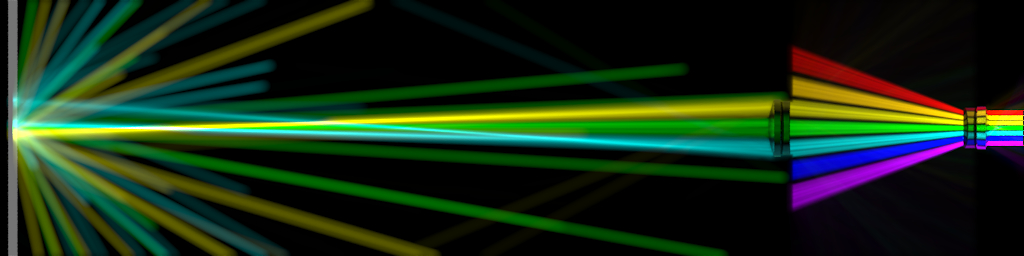
Click on any of the thumbnails to see the full-sized images. If you have an EXR viewer, I strongly recommend looking at the EXRs instead of the jpegs. exrtotiff amplifies pixels that are very dark in the EXRs, at least compare to the way imageview displays them. Also, I find it interesting to look at the scenes at different exposures. For example, the focal point of the lenses shows up nicely as you lower the exposure while the glass of the lenses shows up more clearly at higher exposures.
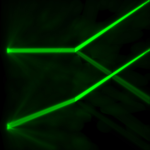
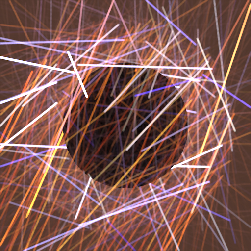
One of the first images I tried to make was light through a vertical sheet of pbrt's glass material. I put a matte sheet along the left edge, a glass sheet along the middle, a tilted spotlight along the right, and setup a scene with the photonmap surface integrator. However, when I tried to render it, pbrt complained it was unable to shoot enough caustic photons. That was bizarre since every ray should have produced a caustic photon. I tried the same scene when the glass had an index of refraction of 1 and got exactly what I expected. After beating my head against pbrt for a long time, I discovered that very low indices of refraction (like 1.001) produced highlights that looked closer to how I expected normal glass to behave. So I put the whole scene inside my ray visualizer and produced the top ray seen in the thumbnail. That made it fairly inarguable that something in pbrt was wrong and I was able to track it down and produce the corrected ray seen in the thumbnail. In general, while debugging my lens images, I found that being able to see the light travel through the scene really helped me understand what was wrong.
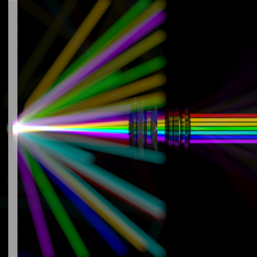
After I was convinced I had working lights and glass objects I set out to produce the lens images I had in my head when I started. This went fairly smoothly. I spent a lot of time with the telephoto lens because it scarred me so deeply during homework 3 and I really like the final image. You can see exactly the two key traits of the telephoto: the very long focal length and the small exit pupil. Of the seven even spaced beams, you can clearly see all except the central ones terminate at the aperture stop while the three that get through go a long way before converging.
Out of curiosity, I tried rendering a few images of the telephoto while varying the distance between the two clumps of lenses. The results were really neat so I rendered a whole bunch of frames and Kayvon helped me make a movie. You can watch the lens' focal point move out as the elements come together and then finally diverge.
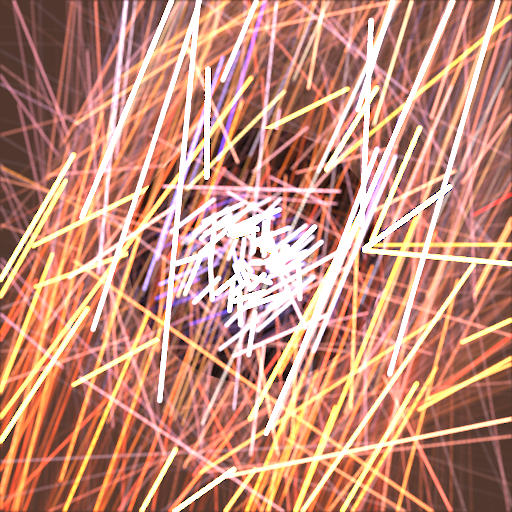
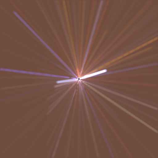
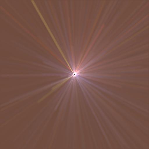
I was thinking about other scenes where displaying the rays would give extra insight into what was happening when it occurred to me I should be able to a neat image of lighting a simple object with a surrounding spherical light source. Then it occurred to me that displaying the rays could be a neat way to show the difference between importance sampling and uniform sampling. The images in the thumbnails show two types of sampling: the first set samples arbitrary rays by choosing an origin unformly in the bounding sphere and then a direction via the same importance sampling as homework 4. The second set always aims the ray at the origin and uses importance sampling to choose the direction. The striking thing about both sets of images is that, at the same exposure, the importance sampling does visibly better at choosing bright rays.
Note: I suggest again using the EXRs instead of the JPGs. As you crank up the exposure you can see all the dim rays the uniform images sample and as you crank it down you can see how much brighter the importances sampling really is (which corresponds directly to how much better it is at sampling bright points).
In all, I found my visualizing volume integrator, both a neat toy and a useful way to understanding why scenes produced the images they did. While talking to Andrew Selle, he mentioned that he had added a similar feature to the raytracer he wrote for Ron's group and that he too had found it very useful.
As for the lenses, I think it would be interesting, but difficult (for software engineering reasons), to adjust pbrt's specular transmision code so that it varied as a function of the colour of light transmitted. With that, it would be interesting to rerender the lens images with the lasers stacked along the z-axis instead of the y-axis. The would start out a single beam and then diverge as they progressed through the lens system. Another avenue to explore is reproducing the long painful phase of homework 3. The images currently allow you to read off the object side focal point and moving the lasers to the other side would reveal the film side focal point. You could then find the focal plane for any film plane by putting two lasers at the same point-- one parallel to the axis and one aimed at the film side focal point.
That's it. Feel free to contact me for any more information or with ideas for other neat scenes. You can peruse all the images here.
A Realistic Camera Model for Computer Graphics by Kolb, Mitchell, and Hanrahan